Tempco Blog articles

Here comes iTempco, the Smart Thermoregulation IoT Platform

Tempco is entering the Industry 4.0 with the iTempco IoT Platform for real time monitoring of industrial thermoregulation plants. Connectivity, big data and analytics are opening new horizons of possibilities in the thermal energy management, enhancing the levels of asset optimization and energy efficiency achievable thanks to the real time condition monitoring of equipments and data process analytics.

The iTempco IoT platform offers a variety of tools for the remote monitoring of equipments, with advanced functionalities of predictive maintenance, service and management of thermal machines, equipments and plants.

IoT termoregolazione 4.0 iTempco

The user receives a hardware interface device pre-installed on the Tempco machinery, that enables the connectivity on the plant. The device provides the harvesting of data aimed to feed the iTempco dashboard for condition monitoring and fault detection, also allowing to adjust and modify remotely the configuration parameters of thermoregulating units and thermal machines.

The IoT applied to thermal energy management machines allows to maximize the production efficiency with costs optimization, increasing as well the equipments’ availability thanks to real time fault detection and data-driven predictive maintenance based on the actual operating status of the plants.

Let’s call it Smart Thermoregulation… are you ready to enter with us the world of Thermoregulation 4.0 with iTempco?

Boiling water in a pot and pitting in plate heat exchangers

A culinary tip gave me a good suggestion to treat the theme of pitting in plate heat exchangers. The answer at this link is indeed really interesting and clever, resolving the question if it’s better to add salt in water when cooking pasta before it starts to boil or when boiling has started. The article, in Italian, states that the proper thing to do is to add salt when water is already boiling, because the bubbles flowing up avoid the salt to deposit on the bottom of the pot, where in contact with the metal surface the solid salt absorbs the heat more efficiently than water, generating a highly corrosive contact surface between salt, water and the metal.

pitting da cloruri acciaio inossidabile

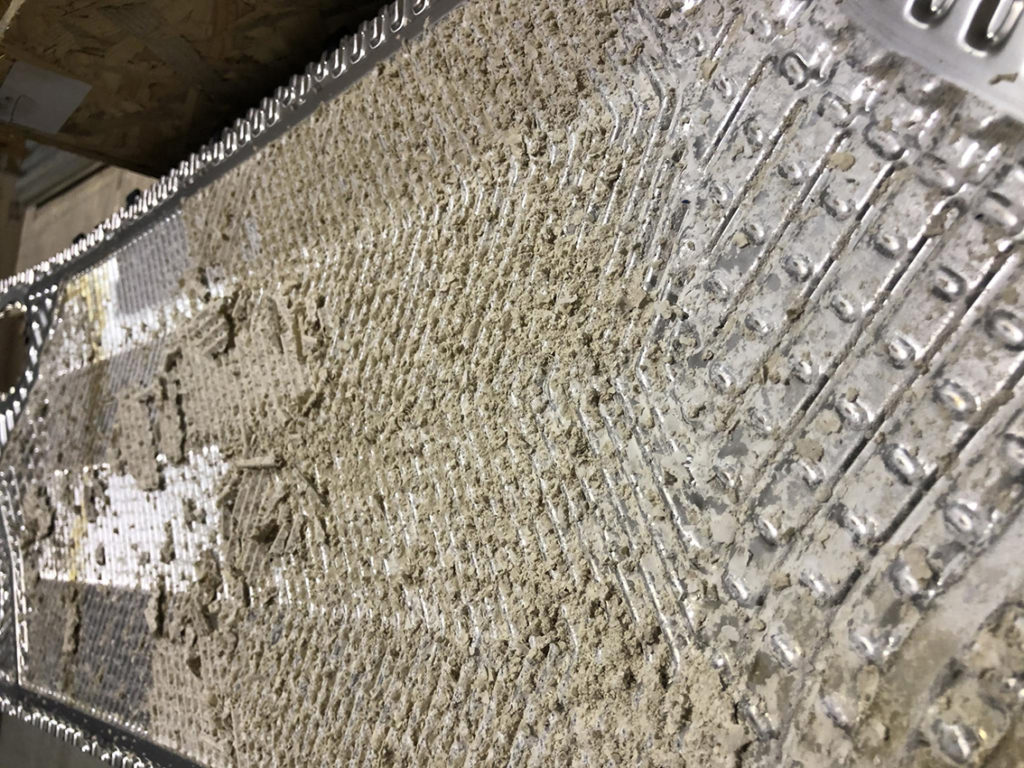
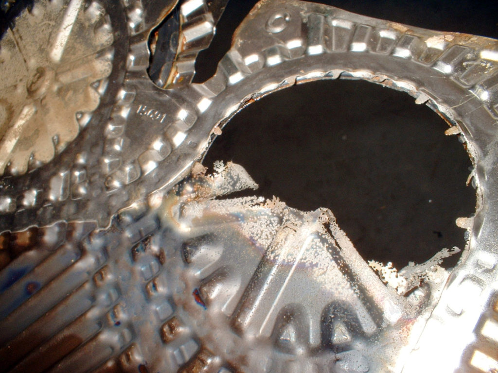
The resulting is pitting, ie a form of very localized corrosion with the creation of small holes in the metal. The case of when adding big salt grains in water during cooking daily habits explains very well the process leading to the pitting due to chloride concentration. We can indeed observe the very same phenomenon happening on plates of heat exchangers, when localized concentrations of corrosive elements (chlorides or other) cause the perforation of the plates.

pitting scambiatori di calore a piastre

Let’s grab an example with anodic oxidation.
In this case the fluid involved is sulfuric acid in high concentration, so that AISI 316 can provide a proper corrosion resistance against the chemical aggression. But it happens that, while the plant is in stand-by, there is product stagnation near the nozzles which leads to a concentration of the acid, causing in a medium-long period the pitting and thus the perforation for corrosion of the plates.

That’s why in this kind of application, and in similar ones, it is suitable to select a more resistant material, such as AVESTA 254 SMO, a type of austenitic stainless steel with high molybdenum content that ensures a specific high corrosion and pitting resistance.

Biogas dehumidification for cogeneration

More on cogeneration in our new tutorial video on the Tempco Youtube channel (turn on subtitles for english). We’re focusing in particular on biogas, one of the most employed fluids in cogeneration plants. Produced from organic waste, the biogas represent an excellent fuel for engines employed for heat and electricity combined generation.

We have here a very virtuous production chain, an example of what is called circular economy, recovering wastes to obtain power generation. Shell and tube heat exchangers are the suitable choice for biogas cogeneration applications. Previous to the proper combustion cycle, the biogas must be treated in order to eliminate all the polluting elements that it gathers and also to extract all the humidity contained, which in case of combustion can damage the engines irremediably.

Biogas treatment include a part of thermal treatment for the dehumidification of these gases, which are usually at the temperature of approx. 34-40° C. The biogas is cooled down using a chiller working at very low temperatures, about 0° C, combined with a shell and tube exchanger with the cold fluid (water and antifreeze) flowing inside the shell. The biogas flows inside the tubes. The tubes are usually straight and sliding to facilitate cleaning operations from deposits that the gas can gather, but also to drain all the water condensed in contact with the cold flow of the glycol water. The condense must drain perfectly and get collected in a condense separator on the outlet of the exchanger.

The application usually requires long exchangers, in order to allow the biogas to flow inside the tubes as long as needed to ensure the complete elimination of all the humidity. Dedicated blowers send then the dehumidified biogas to the engine, and sometimes it can also be post-heated to obtain a proper combustion temperature.

Construction materials are usually carbon steel for the shell, without expansion joints due to the short temperature gap involved. Headers can be as well made of carbon steel, while the tubes can be made of copper. In case the biogas presents high levels of aggressive and corrosive elements, both headers and tubes must have a full stainless steel construction.

The tubes are pressed and, my personal choice, welded, in order to avoid any risk of leaks of glycol water from the shell inside the biogas flowing in the tube section.

Atex thermoregulation in chemical production

Chemical and pharma industry both require a fine and accurate temperature regulation of ingredients and products during the whole production process, as we have already discussed the topic several times yet. In Tempco we’ve recently developed an interesting application for a chemical company, with the supply of thermoregulation units in the production of additives for a series of different chemical products intended for various markets, lubricants, plastic, water and oil. The thermoregulating units are employed on production reactors.

termoregolazione atex impianto chimico

The customer has heat transfer oil available at high temperatures, +270° C, coming from a boiler in the facility, allowing for the development of a heat recovery solution with an oil/oil heat exchanger on the heating circuit, enabling a temperature regulation of products in a range of temperatures between +10° and +200° C. Heating fluid is Therminol 66, while the working fluid is Therminol D12.

The cooling circuit is equipped with a water/oil heat exchanger, receiving water at 30° C from an evaporative tower, pumped into a heat exchanger suited for water at 10°C allowing future further extensions of the thermoregulation range.

regolazione temperatura impianto chimico

The most challenging part of the project was the oil/oil heat exchanger, involving diathermic oil at very high temperatures and thus requiring an accurate evaluation of materials expansion rates, on heat exchangers, pipings and internal connections. We’ve selected special shell and tube heat exchangers with U-tubes design, which allow the tubes to move inside the shell without the need of expansion compensation on the shell itself. All the internal connections are flange joints and/or welded, with expansion compensation joints near the most critical sections for thermal expansion.

The units are in Atex zone 2 IIG execution for explosive environment, and are so equipped with:
– Atex thermostat for maximum temperature level control
– Atex pressure switch for maximum pressure level control
– Atex temperature sensor with 4-20 mA transmitter
– three port ON/OFF valve for heat/cold exchanger selection DN125, complete with a pneumatic actuator and shuttle valve
– Two port ON/OFF valve on water cooling circuit, complete with pneumatic actuator and shuttle valve
– Two port modulating valve on Therminol 66, complete with modulating electro-pneumatic actuator
– Two port ON /OFF valve for Therminol 66 isolation complete with pneumatic actuator and shuttle valve

Usually, this kind of applications have narrow installation spaces, so that we had to make the thermoregulating unit as compact as possible. At this purpose we installed the exchangers sloped, and it implicated special customized pipings with tailored components and additional evaluations such as material expansion projected on the angle ratio, the correct evaluation of angles in order to ensure the proper functional drainage and internal sections of the exchangers suitable for a sloped installation, and also special support structures which allow the heat exchangers to move for expansion compensation.

termoregolazione atex industria chimica

Finally, the flange connections are not only intended to avoid oil leaks, a very critical event in case of Atex environments, but they also provide an easy installation. Flange connections guarantee indeed to obtain correct installment values, while in case of threaded connections one or two thread rotations are enough to get off quota, increasing in addition the risk of oil leaks.

industria chimica centralina termoregolazione

T COIL dimple jacket aka flexibility in thermoregulation

A new video in our Youtube Tempco channel (turn-on subtitles for English translation) is dedicated to a very interesting argument, a special kind of heat exchangers called T COIL. These are dimple jacket exchangers which are customized by design upon specific requirements of final applications.

T COIL dimple jacket exchangers are primary exchangers offering high efficiency and flexibility, and are realized by welding on their edges two metal sheets, also spot-welded according to a scheme depending on the kind of the flowing fluid to be employed. The welded sheets are then inflated using high pressure, obtaining a dimple with a series or internal channels where the cooling or heating fluid will flow. The sheets are usually made by AISI stainless steel, allowing cold deformation after welding without breaking.

This peculiar construction process allows to obtain a high mechanical resistance, so that materials with thin thickness can be employed. This characteristic allows to reduce costs while having excellent thermal exchange rates, lower inertia and thus higher thermal efficiency. T COIL series exchangers can be employed by direct immersion into the fluid to be cooled or heated, but also with clamp-on installation on tanks, pipings or machinery. They can work with a variety of fluids, such as steam, heat transfer oil, water and overheated water.


Industrial applications really are countless, in Tempco we already used T COILS in the food industry, chemical and pharmaceutical sectors, but also in the paper mill industry, and every year we develop and discover new applications in further sectors. Starting with the early applications for water thermoregulation, step by step we’ve got very further, for grain cooling, dust cooling or clamp-on applications on tanks in substitution of traditional cooling coils.

We are able to realize T COIL dimple jacket exchangers in standard sizes, the only limit being the sizes of metal sheets and coils available on the market. Our workshop can realize plates and exchangers with customized dimensions according to every application needs, offering different shapes and geometries to fit customer’s requirements and industrial processes’ thermoregulation needs. This construction flexibility allows to adapt T COIL exchangers to a wide variety of heating and cooling tasks in production processes.

Mechanical seal troubleshooting part 2

Chapter two on the topic of how to detect and recognize the causes of mechanical seal troubles, after the post dedicated to the problems related to lubrication. Mechanical seals can undergo a series of different kind of wear. An irregular wear can be the consequence of an excessive wear on bearings and in presence of vibrations.

usura tenute meccaniche

Small amounts of tough particles in the fluids can also lead to corrosion on mechanical seals: by sedimenting on the seal’s surface, these particles act like cutting tools in a grinding machine, damaging contact surfaces. An intermittent spotted wear on the seal surface can also relate to an imperfect linearity of the seal surface itself, due to defective mechanical construction of the seal, or even due to a wrong mounting.

usura faccia tenute meccanicheusura intermittente facce di tenuta

Mismatched materials and fluids
The right choice of seal’s materials is essential to ensure a long mechanical seal working lifetime, enabled by the compatibility between the seal’s material and the pumped fluids. A wrong matching can lead to swelling problems in elastomers, boosted by the high temperatures and the long exposure periods involved. Corrosion on mechanical seals can also be provoked by the incompatibility between materials and fluids, deteriorating the seal surfaces.

swelling elastomericorrosione tenute meccaniche

Installation and connections
The correct installation is also a key factor to preserve the conditions of a mechanical seal. Pictured here are two examples of damages related to a wrong installation of the seal, leading to cut or damaged OR and breakage of the seal ring.

OR danneggiati tenute meccanicherottura anello di tenuta

Also the working pressure of the pump must be comprised in the range of design values of the mechanical seal. In case of excessive pressure, the seal can be damaged irreversibly. At last, pay attention to the rotation verse of the pump, to avoid a breakage of the spring. This breakages can happen with a wrong electrical connection of the engine, a pump installed in parallel without a check valve, or also with a return flow when the pump is off.

danni da pressione tenute meccanicherottura molla tenute meccaniche


The Tempco Service is at your disposal to solve any doubt or needs.

Exhaust heat recovery in cogeneration with shell and tube exchangers

Let’s finally talk about shell and tube heat exchangers, employed in cogeneration applications. Many times we’ve had already spoken about cogeneration, and this new video on our Tempco Youtube channel (turn on subtitles) is dedicated to exhaust heat recovery from cogeneration engines.

A cogeneration plant is usually equipped with an endothermic engine driving a generator to produce electricity. Cogeneration stands for power and heat generation at the same time, also leveraging thermal energy produced by the engine. This is possible thanks to heat recovery achieved by a shell and tube heat exchanger on the exhaust fumes circuit.

Exhaust coming as waste from the endothermic engine in cogeneration have very high amounts of energy, making thermal recovery really advantageous instead of dissipating the heat. Here exhaust are at very high temperatures, typically between up to 550 and 650° C depending on the kind of engine and fuel employed.

For cogeneration heat recovery applications, shell and tube heat exchangers are suitable with straight pipes to allow cleaning operations, because exhaust can contain particles from combustion requiring some periodical cleaning maintenance. Construction material is usually stainless steel, especially for pipes and headers being in direct contact with exhausts. Diesel oil, biogas and methane exhaust can indeed contain acid elements exposing the components to corrosion, an even higher risk in case of high temperature conditions of cogeneration plants.

scambiatore fascio tubiero cogenerazione

Working with high temperatures, heat recovery cogeneration applications thus also require special construction tricks: aimed to avoid failures due to thermal expansion, with unwanted side effects such as leaks, all the tubes are welded and pressed on headers, while the shell, which allows water flow employed for thermal recovery, is equipped with a thermal expansion joint to compensate the expansion gap between the shell, with water at temperature of approximately 90°, and the tube.

testata scambiatore fascio tubiero cogenerazione

Mechanical seal troubleshooting

Mechanical seals employed in machinery with rotating components can be affected by a series of wear issues. The main cause of mechanical seal problems is related to the correct lubrication of the seal itself. These are the main signs and causes of a scarce or wrong lubrication in mechanical seals aiming to a proper troubleshooting.

Dry running
Dry running happens when there is no liquid at all around the mechanical seal. The absence of the liquid film generates friction between the faces of the seal, with a dramatical increasing of the temperature. The typical damage of dry running is the presence of burned elastomeric parts. The damage happens when the O-ring is in direct contact with the over-heated mechanical seal ring.

tenute meccaniche funzionamento a secco


Insufficient lubrication
A scarce lubrication can happen when the pumped fluid has a very low viscosity, or when temperature at atmospheric pressure is higher than boiling point, or if there is some air in the circuit. In these cases, the heat caused by the friction can concentrate on small areas on the seal surface, with the result of even extreme heating conditions. Local alternation of heating and cooling of the mechanical seal surfaces can cause small radial cracks due to the thermal shock.

tenute meccaniche risoluzione problemi


Absent or scarce flow
It happens when the pump circuit is working with the inlet valve closed. Heat generated by the friction on the shaft seal can generate very high temperatures. The temperature increase can thus damage elastomeric parts of the mechanical seal. In addition, it increases the risk of dry running on the surface of the mechanical seal.

tenute meccaniche troubleshooting


Further mechanical seals problems can also be related to installation issues, failure in components or a wrong selection in materials matching. We will dedicate another article to analyze in depth the troubleshooting of these cases.


Plates H and L, choosing corrugation in heat exchangers

A new video is up on our YouTube Tempco channel (subtitles option available), dedicated to the kind of plates H and L in plate heat exchangers. H and L plates stands for high and low efficiency, referred to the thermal exchange rate achievable. Thermal transfer efficiency in a plate heat exchanger is indeed a result of the turbulence rate of fluids, depending upon the kind of Chevron angle in the plates corrugation design.

The Chevron angle in H plates is a dull angle, so that when overlapping the plates, rotated by 180° on each other, there will be many contact points leading to a very high thermal transfer rate. By the way, pressure drop will also increase.

That’s the reason why L plates are also available, having a more acute angle in the herringbone design of the corrugation. This goes with less contact points in the plates overlap, reduced pressure drop and also a lower efficiency in thermal exchange.

L plates are suitable for heat transfer applications using viscous fluids, not requiring very high thermal exchange rates.
H plates are suitable to obtain high thermal exchange efficiency with high pressure drop allowed, thus having pressure of a recirculation pump.

How to choose H or L plates in a heat exchanger? The selection is easily done by introducing the design values in a software to calculate a heat exchanger, values such as maximum pressure drop allowed, kind of fluids involved and their inlet/outlet temperatures. The software then determine the kind of plates, often suggesting the right mix between H and L plates in order to achieve the best compromise of heat transfer efficiency and pressure drop for the specific application.