Tempco Blog articles

Fluids and carbon steel in plate heat exchangers

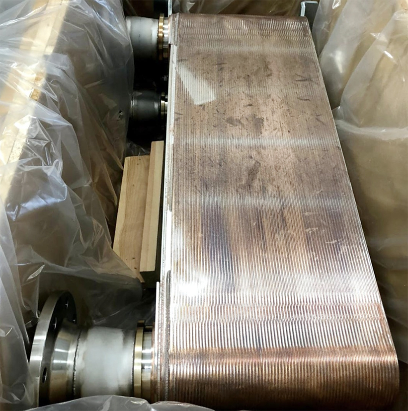
How connections on plate heat exchangers are made to avoid contact between the fluid and carbon steel? This is a question that I’m often asked for.

If the fluid employed within the exchanger presents no particular problems in getting in contact with carbon steel, the fluid entering the flange of the exchanger gets then in direct contact with the material. Thereafter, it enters the exchanger and here it gets in contact with the stainless steel of the plates. But very often, it is necessary to avoid the contact of the fluids with components and materials that are prone to oxidation and corrosion. In this case, it is mandatory to avoid any possible contact of the fluid with carbon steel

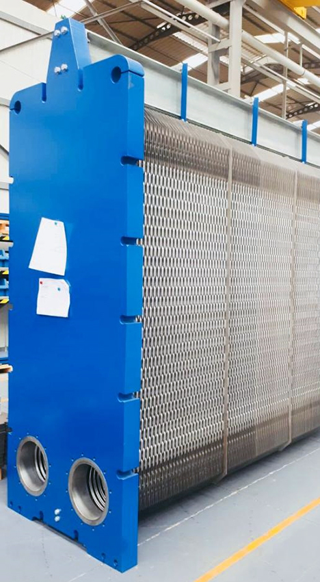
Plate heat exchangers can have two main connection options, with flanged or threaded connections. Flanged connections make the trick quite easy, in fact it’s sufficient to coat the body in the nozzles area using elastomers, such as nitrile, ethylene-propylene or viton, or using stainless steel AISI 304 or AISI 316. The inner part of the body in the nozzle area is protected as well by this lining. The gasket of the first plate gets then in contact with the circular ring of this lining, so that the fluid flowing through the body enters between the first two plates, never getting in contact with carbon steel. The final plate is a blind plate, so it never gets in contact with carbon steel either, remaining always in contact only with the plates in stainless steel.

Speaking of it, fluids never flow between the first plate and the body, they always enter directly between the first two plates.

On plate heat exchangers with threaded connections, the nozzles – made in stainless steel or using plastic materials in case of aggressive fluids such as sea water or acids – have a sort of counterpart which gets in contact with the gasket, and is held back by the body. So that here as well the fluid entering the exchanger gets only in contact with stainless steel and the materials of gaskets. Never getting in contact with carbon steel, paint or other materials that are prone to corrosion.

Finally, the problem doesn’t even exist in plate heat exchangers for food and beverage applications, where hygienic requirements force to employ full stainless steel executions.

Stay updated on the latest applications by subscribing our monthly Tempco Newsletter – Solid Temperature.

Immersion cooling and towers in die casting foundry

Back in 2011, Tempco installed a cooling plant for an important Italian foundry. The cooling plant provides in fact the cooling of several equipments, including induction furnaces, die casting machines for the foundry of metallic parts with steel dies, moulds cooling tanks and cooling tanks for the manufactured parts.

Overall, the cooling plants is composed by:

Tempco raffreddamento fonderia torre di raffreddamento


After more than 10 years of operations, the customer needs to increase the production capacity of the plant. The intervention involved to double the cooling tower and the related water distribution system, due to the fact that the foundry will install new additional induction furnaces and also because the cooling system will have to serve also a new part of the plant aiming for the cooling of die casting machines.

Tempco raffreddamento fonderia conchigliatrici parti metalliche

Tempco raffreddamento fonderia scambiatori TCOIL a immersione

Tempco raffreddamento fonderia scambiatori saldobrasati


Stay updated on the latest applications by subscribing our monthly Tempco Newsletter – Solid Temperature.

How to calculate a thermal buffer tank in process cooling

How a thermal buffer tank gets calculated, and what it is aimed for? Buffer tanks, or inertial storage tanks, are employed in cooling systems with thermoregulating units served by chillers. Very often, indeed, our thermoregulating units, or thermostatation units, are served by chillers to serve utilities such as pharmaceutical reactors or industrial processes in general. These cases involve high temperature gaps, requiring within the same process cooling tasks, heating and maintaining a certain temperature.

Let’s do an example of a pharmaceutical reactor where a product has to be heated at a high temperature, for example 90° C, in order to achieve a certain chemical reaction. Once it’s done, the product has to be kept at a certain high temperature for a defined time lapse, and then cooled. We have therefore a high volume amount of product at high temperature and a jacket of the reactor with a circulating fluid at a high temperature as well, and it all has to be cooled. What happens is that the thermoregulating unit closes the heating section and opens the cooling section, by means of a valve, a 2-way, 3-way, switching or on/off valve, on the exchanger.

The refrigerating group is sized in order to achieve the cooling of that exact mass volume of product within a defined time lapse. But as soon as the cooling process starts, we suddenly have an enormous amount of fluid at high temperature entering the exchanger, where cold water flows on the secondary circuit. The exchanger will therefore transfer a huge amount of thermal energy, due to the fact we have a very high logarithmic mean temperature difference, that increases the efficiency of the exchanger. The overall amount of thermal energy gets then discharged upon the cooling water, and in case there is no availability of a storage tank with an important volume the risk is to put the chiller under a high stress.

This is because, if we have a limited volume available, all of this energy gets dumped inside the cold tank, and the water, instead of returning the chiller at a temperature of 15° C, for example, to be cooled at 10° C, comes in at a temperature of 40-45° C, or also 50° C for a transient. Which is enough to bring the evaporation pressures of the chiller out of its working range, thus blocking the refrigerating group and stopping the cooling process required by the production.

It is therefore very important to properly calculate the volume of this storage tank, or buffer, in order to have an inertial tank able to diminish these peaks. Allowing to provide water to the chiller at a temperature that doesn’t create a stressing task. The calculation is made by considering the mass volume of the product, and then the amount of energy, maintaining a margin on the volume of this tank in order to ensure that, during these peaks, the temperatures remain within the operating range of the chiller, 20-25° C, 30° C at maximum.

At this purpose, it’s important that the customer helps providing all the basic informations about his plant, such as the volume of circulating water, the length of pipings, the volume of the reactors, in this case, and the speed required to achieve the cooling process. This is all necessary to correctly size the dimensions of the chiller. Finally, it is also helpful to have a 3-way switching valve on the cooling section of the thermoregulating unit, allowing to set a temperature ramp that respects the temperature and the time lapse of the customer, and allows the chiller to work properly without going under excessive stress.

Stay updated on the latest applications and subscribe here to our monthly Tempco Newsletter – Solid Temperature.

Multi pass plate heat exchanger for hydraulic power unit

Pictured here below is an important plate heat exchanger, that Tempco has supplied to serve a hydraulic power unit. This is a quite remarkable machinery, as easily arguable from its main characteristics:

  • Oil flow rate of approx. 2.500 lt/min ISOVG46
  • Cooling water at medium-high temperature with limited flow rate
  • Installed power capacity of approx 1.700 KW

The limited flow rate of the cooling water has in particular involved a demanding thermal scheme. The application required indeed the engineering and realization by Tempco of a special multi pass plate heat exchanger with DN200 connections. The exchanger is equipped with plates with a thickness of 0,6 mm and NBR HT gaskets.

Finally, the equipment is in PN16 execution.

Tempco scambiatore multi pass Centrale idraulica

Stay updated on the latest applications and subscribe here to our monthly Tempco Newsletter – Solid Temperature.

Wind chill and evaporative towers

When I try to explain how evaporative towers work, I often find myself speaking about that particular effect called Wind chill, also useful to show the advantages of cooling towers compared to indirect heat exchangers.

The wind chill, or cooling effect caused by the wind, refers to that sensation of chilling coming out from a swim in the sea in the presence of wind. This sudden and intense sensation of cold is caused by the evaporation of water over our body, and this is due to the effect of evaporation of water on our skin that absorbs calories, energy.

This is exactly the same effect that happens in adiabatic coolers and evaporative towers, that allows to cool water at a temperature level lower than the temperature of ambient air. In fact, speaking about evaporative towers with customers, we always ask them the value of design wet bulb temperature, which is essential aimed to design and calculate the cooling tower.

Watching US’ standard ASHRAE tables, or also other climatic tables, there are always average dry bulb temperatures indicated referred to different geographical areas, both during the winter and summer season. These tables contain as well a column with the respective average values of wet bulb temperature.

Making it simple, wet bulb temperature is the temperature that is obtained wrapping the sensor, or bulb, of a common outdoor thermometer with a slightly humid rag. Suddenly it will be possible to see the temperature’s level going down, and this is the wet bulb temperature, that is the temperature of the bulb humidified, which is lower than ambient external air temperature. This is as well the reference temperature employed for the design of cooling towers, because that’s the lowest temperature that can be achieved, obtaining water coming out of the tower at a lower temperature. It happens taking advantage of the latent heat of vaporization, which is the energy that gets dissipated by water to evaporate, generating a decrease of the temperature of the water that gets cooled.

Stay updated on the latest applications and subscribe here to our monthly Tempco Newsletter – Solid Temperature.

Cooling for power inverters in Russia with special shell and tube exchangers

We have recently supplied a series of shell and plate heat exchangers aimed for the cooling of power inverters, according to the special requirements received by the engineering company that commissioned the plant.

The final location of the application is in Russia, where EAC certification is required for industrial equipment installation, which in Tempco is available as a standard option on our full offering of heat exchangers.

Scambiatori fascio tubiero raffreddamento inverter EAC

The shell and plate exchangers employed present in addition a particular construction, because the tube array inside the exchanger is made using a series of tubes with a spiral shape, aimed to achieve a double target:

  • increase of thermal transfer rates thanks to the turbulent flow of fluids
  • thermal expansion compensation ensured by the particular shape of the tubes

Scambiatori fascio tubiero raffreddamento inverter Russia

Scambiatori fascio tubiero EAC raffreddamento inverter

The exchangers are completely constructed using stainless steel.

Stay updated on the latest applications on thermal energy management and subscribe here to our monthly Tempco Newsletter – Solid Temperature.

Double wall exchangers and oil hydraulics

Double wall heat exchangers are a particular kind of exchangers that is also employed in oil hydraulics applications. The main characteristic of these exchangers is to have a double plate, or double wall, to avoid the possibility of mixing between primary and secondary fluid in case of breaking, corrosion or perforation of the plates.

This kind of exchangers is employed in hydraulics plants especially in case of extremely sensitive applications. An example is the cooling of the hydraulic oil of a gearbox in a turbine for power generation, where the mechanical component is a core part of the application. In this case, having the presence of water within the oil leads to irreparable damages.

The most common solution employs tube-in-tube shell and plate exchangers, double tube then, or double wall. These exchangers have special heads that, in case of leakage of fluids, allow the leakage to flow within a special chamber between the two heads. Allowing the detection of the leakage and a prompt repair intervention.

In case of double wall plate heat exchangers, the presence of a double gasket in the nozzle area avoid the possibility of fluid’s mixing. In case of breaking of a gasket, indeed, along the external perimeter of the exchanger or in the nozzle section, the leakage flows towards the outside of the exchanger. In case of cracking of a plate, there is an air chamber passing between the two plates, with therefore a visible leakage of fluids toward the outside, making it easy to repair it.

Advantages and disadvantages of the double wall solution. The advantages are all related to the security, making double wall exchangers a mandatory choice when is strictly necessary to avoid any possible mixing between the primary and secondary fluid, in this case hydraulic oil and water. The disadvantages are many, on the other side, first of all the higher costs due to the fact that the number of plates gets duplicated. Thus increasing the amount and costs of construction materials. In addition, having a higher thickness and an internal chamber air between the two plates, the thermal transfer coefficient rates are lowered. And so, not only a higher amount of construction materials is needed, but also the thermal transfer surface must be increased, in order to achieve the same thermal duty. Anyway, it remains a necessary solution to prevent any possible problem of fluid’s mixing, protecting the oil hydraulic plant from serious issues.

Stay updated on the latest applications and subscribe here to our monthly Tempco Newsletter – Solid Temperature.

Carbon-ceramic brakes cooling plant revamping

Carbon-ceramic brakes are with no doubt one of the excellences of the Italian industry and very well recognized all over the world.
From high-performance racing cars, to blazoned hyper cars, through high-speed aircrafts and trains, all of these systems employed in the automotive and aerospace sectors need braking solutions that ensure top-level and best in class performances.

Tempco has realized about 12 years ago a first plant for the cooling of furnaces for high temperature processing of carbon-ceramic discs. Since then, the plant performed flawlessly. By the way, later on we have also implemented a new plant with almost twice the power capacity, updated to the state of the art of technology available today, equipped with efficient control technologies and advanced monitoring systems.

raffreddamento forni freni carboceramici

After two years of operations of the second enhanced plant, the customer wanted to reply the new technologies also on the first plant installed. During the break for the holidays at the end of the last year, we’ve worked providing a deep revamping and boosting, by introducing a new control system equipped with a PLC and an operator panel, adopting the management software and the instruments successfully tested over the last two years.

After 10 days of intensive work, the new enhanced plant has finally been completed with positive start up and testing.

Stay updated on the latest applications and subscribe here to our monthly Tempco Newsletter – Solid Temperature.

Mechanical and engineering advantages of plate exchangers in hydraulics

In addition to the thermodynamic advantages offered by plate heat exchangers in hydraulics applications, in substitution of shell and plate exchangers, there are also other main advantages related to mechanical and installation aspects.

In hydraulics, the goal is to maintain at a certain temperature level the oil, which provides mechanical work in operating machines. A plate heat exchanger is much more compact then a shell and plate exchanger with the same thermal capacity, with clearly a direct impact on the size of the hydraulic units within the plant, which will be smaller and more compact.

Another huge advantage is the fact that all of the four nozzles are placed on the same side of the exchanger, two for the water and two for the oil. This allows to build the depth of the exchanger based on the thermal capacity required. It permits machine builders and plant builders to make some standardization, which means that they can adopt a standard layout employing a certain kind of exchanger, and depending on the power capacity of the pumps installed they can increase or decrease the number of plates with no variations to the design of the piping.


Moreover, the use of plate heat exchangers instead of shell and plate ones in hydraulics makes maintenance and substitution operations easier: is it indeed sufficient to disconnect the piping located on the same side of the exchanger, extract the old exchanger and insert the new one. In addition, in case of big hydraulic plants, where a switch from brazed plate to inspectable plate exchangers is required, this advantage is even more evident due to the fact that it allows to correct possible mistakes on the engineering, or facing increases in power capacity. This is possible because an inspectable plate heat exchanger can be easily expanded by increasing the number of plates, with no variations on the piping layout and thus offering great flexibility.

To solve a similar issue having a shell and plate heat exchanger on a hydraulic plant leads to great problems instead, because the new exchanger will be longer, or bigger, with a different shell, forcing the machine builder or the plant engineer to revise the overall layout of the piping.

Subscribe here to our monthly Tempco Newsletter – Solid Temperature.

Heat exchangers super-enabled by additive manufacturing

The attraction and elective affinities between heat exchangers and additive manufacturing are very strong and getting more and more triggering, as it’s clear to see while reading this interesting article published by All3dp focused on the many advantages that 3D printing brings into the world of heat exchangers. While designing and developing more efficient heat exchangers for cooling and heating tasks in industrial processes, there are indeed two main targets: increasing the thermal transfer surface and reducing at the same time the pressure drops.

The total design freedom offered by additive technologies allows the complete re-imagining the design of heat exchangers.

Tempco scambiatori saldobrasati

The source article mentions the example of a recently developed prototype of heat exchanger realized by GE Research called UPHEAT – Ultra performance heat exchanger enabled by Additive technology: this heat exchanger can handle temperatures up to 900° C, which means 200° C above the maximum level that actual heat exchangers can stand. GE Research says the exchanger could find applications in the energy sector, enabling a more efficient and cleaner power generation.

Metal additive manufacturing is as well the focus of R&D in the aerospace sector, where metal 3D printed single piece heat exchangers are being developed for the NASA and the US Army, also enhanced thanks to topological optimization, using metal 3D printers by Fabrisonic and 3D Systems.

Scambiatori di calore additive manufacturing 3D Systems

3D printing brings indeed a series of main advantages for the production of heat exchangers, allowing to manufacture lighter devices, more compact and performing, while increasing efficiency and reliability. First of all, additive manufacturing could revolutionize the production process of heat exchangers, allowing the manufacturing of the plates pack and the manifold in a single piece, requiring no more extra steps of forming, assembly, brazing or welding. Reducing not only the production cycle time but also increasing the lightness and the robustness of the overall structure.

Using additive manufacturing is furthermore possible to create any imaginable kind of shape and geometry, opening a virtually unlimited design landscape for the creation of unique and customized shapes and internal geometries, also leveraging breakthrough techniques such as generative design. Also heading to the miniaturization of components and devices, aimed for narrow spaces applications which are very often required as we see in Tempco, and not just in the motorsport and aerospace sectors mentioned in the article.

The possibility to create in AM extremely thin thermal exchange walls finally drastically increases the amount of thermal transfer surface, boosting the efficiency of the thermal machines. In addition, AM can create heat exchangers using a wide range of materials, ranging from aluminium alloys to high conductivity copper and copper alloys, and all the way up to high-temperature alloys such as Inconel 718 and Inconel 625. Eventually allowing the manufacturing of multi-material heat exchangers as showcased by the heat exchanger developed by Gen3D, a software developer for AM applications, in collaboration with 3D printers manufacturer Aerosint using laser powder bed fusion technology. This special heat exchanger combines the high-conductivity advantages of a copper alloy employed for the internal surfaces of the exchanger with those of a high strength steel on the outside.

scambiatori di calore additive manufacturing

Subscribe here to our monthly Tempco Newsletter – Solid Temperature.